

HiltonC
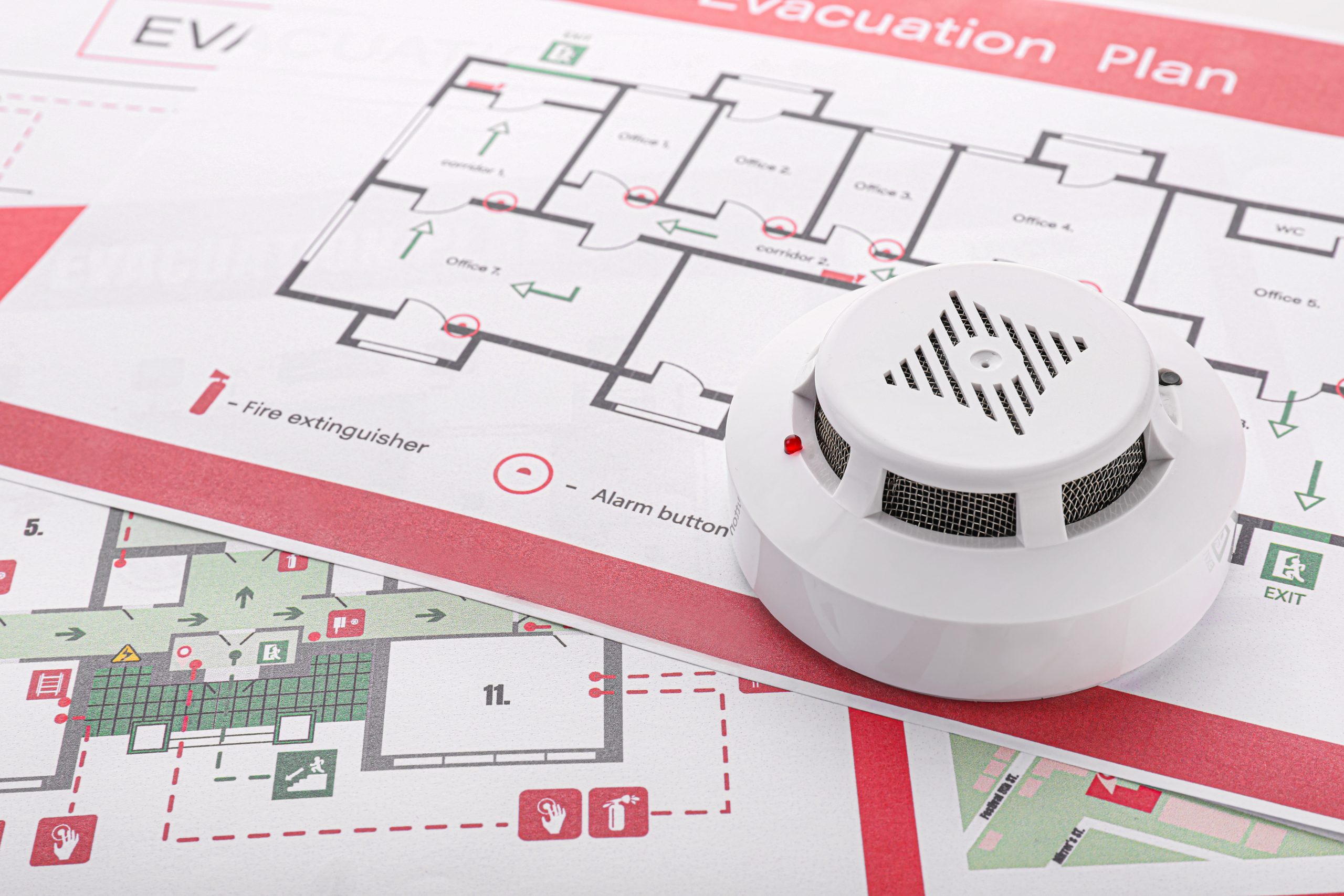
Walk into most industrial facilities and you’ll find gas detectors. Flame detectors. Heat detectors. A full alphabet of sensing hardware mounted to structural steel, process skids, and cable trays. The equipment checks out. The wiring is clean. And then a flammable gas release occurs in a corner of the unit the system was never actually designed to cover — and nobody finds out until after the incident review.
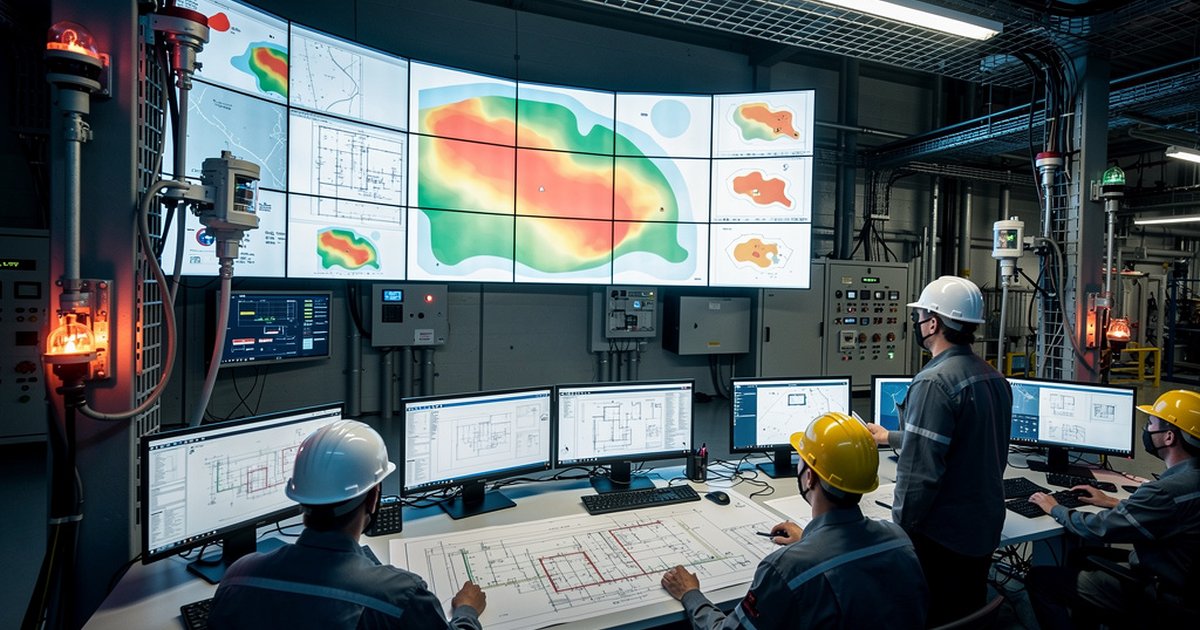
Fire and gas detection mapping is the discipline that prevents that outcome. It is not a vendor selection exercise. It is not a matter of spacing detectors at regular intervals and calling it done. It is an engineering process — one that starts with hazard analysis, works through coverage geometry, and ends with a documented, defensible design that can be tested, audited, and maintained. Most facilities skip most of it.
What F&G Mapping Actually Is
Fire and gas mapping is the systematic process of determining detector type, quantity, and placement to achieve a defined coverage objective across all credible release and ignition scenarios in a facility. The goal is not to install detectors — it is to achieve a specified probability of detection for defined hazard scenarios before those scenarios escalate.
That distinction matters. A facility can be populated with detectors and still have significant coverage gaps. Detectors mounted where process equipment blocks line-of-sight, where prevailing wind consistently carries gas plumes away from sensor locations, or where structural obstructions create dead zones — these are design failures, not hardware failures. The hardware works exactly as specified. The problem is the specification itself was never grounded in hazard geometry.
The governing technical frameworks for F&G mapping in industrial settings include NFPA 72 (National Fire Alarm and Signaling Code) for fire detection system design, and ISA-TR84.00.07 for the risk-based, coverage-based methodology applied to gas detection in process environments. Saudi Aramco facilities are additionally governed by applicable SAES requirements, which establish mandatory detection coverage in classified hazardous areas consistent with IEC 60079 zone classifications. Understanding how these frameworks interact — and where each takes precedence — is a prerequisite for competent F&G system design in the Kingdom.
The Three Coverage Approaches
ISA-TR84.00.07 identifies three principal approaches for establishing and demonstrating adequate F&G coverage. Each has a different analytical basis and a different level of rigor. Choosing the right one depends on the consequence severity of the target scenario and the regulatory expectations of the jurisdiction.
Geographic coverage is the simplest method. Detectors are positioned to achieve a defined percentage of physical area coverage within a target zone, typically verified using a detector placement tool or geometric analysis. It does not account for the physics of gas dispersion or flame radiation — it is an area-based proxy. For low-consequence areas with simple geometries and well-characterized hazards, it can be appropriate. For complex process units or high-consequence scenarios, it is rarely sufficient on its own.
Scenario-based coverage moves from geometry to physics. It identifies credible release scenarios — specific hole sizes, leak locations, and release rates derived from process hazard analysis — and evaluates whether the proposed detector layout would detect each scenario before the gas cloud reaches a hazardous concentration at an ignition source. This approach requires dispersion modeling, typically using tools such as PHAST or similar consequence analysis software, and is significantly more defensible under audit.
Risk-based coverage is the most rigorous method. It explicitly quantifies the risk reduction provided by the F&G system — expressed as a probability of detection for defined scenarios — and evaluates that reduction against a target risk criterion. This approach integrates with the facility’s Layer of Protection Analysis (LOPA) and positions the F&G system formally within the Safety Instrumented System (SIS) framework. It is increasingly expected by sophisticated operators and is the methodology of choice for high-hazard process units in refinery and petrochemical settings.
Detector Technology Selection
Coverage methodology determines where detectors go and how many are needed. Technology selection determines whether those detectors can actually perform their function in the environment they’re placed in. The two questions are related but distinct, and conflating them is a common design error.
For flammable gas detection, catalytic bead (pellistor) sensors are the conventional technology for well-ventilated areas with lower risk of sensor poisoning. Infrared point detectors offer improved resistance to catalyst poisoning and are preferred in environments with halogenated compounds or silicone-based process fluids that can degrade catalytic sensors. Open-path (line-of-sight) infrared detectors cover large areas with a single beam and are effective for monitoring the boundaries of classified zones, but their performance is sensitive to beam alignment and fouling of optical surfaces.
Ultrasonic gas leak detectors respond to the acoustic signature of a pressurized gas release rather than gas concentration, making them effective for detecting high-pressure leaks quickly regardless of wind direction — a meaningful advantage in outdoor process areas where gas dispersion is highly variable. They do not replace concentration-based detectors; they complement them.
For flame detection, ultraviolet (UV), infrared (IR), and combined UV/IR detectors each have specific spectral sensitivities and specific false-alarm vulnerabilities. UV detectors are sensitive to solar radiation and arc welding. IR detectors can be triggered by hot surfaces and certain process emissions. Multispectrum IR detectors reduce false positives significantly and are standard practice in high-activity process environments. The selection must be matched to the expected fire signature of the target fuel — a hydrocarbon pool fire has a different spectral signature than a hydrogen jet fire, and the detector specification must account for this.
Integration with the Safety Instrumented System
F&G detection does not operate in isolation. In a process facility, the detection system is typically integrated with emergency shutdown (ESD) logic, deluge and suppression system activation, HVAC isolation, and alarm management — all of which interact with the facility’s Safety Instrumented System. This integration introduces additional engineering requirements that the F&G mapping exercise must account for.
Voting logic — the configuration determining how many detectors must be in alarm before an automatic action is initiated — is one of the most consequential design decisions in the system. A 1-out-of-1 (1oo1) voting arrangement initiates action on any single detector alarm, maximizing sensitivity but maximizing false-trip exposure as well. A 2-out-of-2 (2oo2) arrangement reduces false trips but introduces coverage gaps if one detector fails. A 2-out-of-3 (2oo3) arrangement is the standard configuration for high-consequence initiating events in most industrial SIS designs — it provides both false-trip resistance and single-fault tolerance. The voting architecture must be defined before the detector placement exercise is complete, because it directly affects how many detectors are required to achieve the target detection probability in each zone.
Response time also requires explicit engineering attention. The time from detection to initiation of a protective action must be evaluated against the consequence escalation timeline for the target scenario. A gas cloud that reaches its lower flammable limit (LFL) at an ignition source in 45 seconds requires a fundamentally different detector density and voting logic than one with a three-minute escalation window.
Common Design Failures
Most F&G system deficiencies encountered in third-party audits fall into a predictable set of categories. Recognizing them is the first step to designing around them.
- Detector placement based on convenience rather than coverage: Detectors mounted at accessible locations on existing structural steel, without reference to hazard locations or dispersion modeling.
- No credible release scenario basis: Coverage claimed without reference to specific hole sizes, release rates, or process inventories from the facility’s PHA or HAZOP.
- Technology mismatch: Catalytic detectors specified in environments where sensor poisoning is a foreseeable operating condition, or UV flame detectors in areas with regular arc welding activity.
- Undocumented coverage assumptions: No F&G mapping report, no coverage calculation, no basis of design. If the facility cannot demonstrate what coverage it has, it cannot demonstrate that coverage is adequate.
- SIS integration not formally evaluated: ESD voting logic and F&G initiating events not reflected in the facility’s SIL assessment or LOPA, leaving the system’s actual risk reduction contribution unknown.
What a Defensible F&G Mapping Package Looks Like
A complete, auditable F&G mapping deliverable for a process facility includes: a defined coverage philosophy and target detection probability for each zone; a credible release scenario register linked to the facility’s PHA or HAZOP; detector technology selection with documented basis for each area; a coverage calculation or dispersion model demonstrating that the proposed layout achieves the target; voting logic definition and its integration with the ESD/SIS cause-and-effect matrix; and a test and maintenance plan that can be implemented under normal operating conditions without defeating coverage.
That documentation set is what a Saudi Aramco project audit will look for. It is what a Saudi Civil Defense inspection of a major industrial facility increasingly expects. And it is the minimum standard for any operator who wants to demonstrate that their F&G system is an engineered safeguard — not a regulatory checkbox.
Bottom Line
Fire and gas detection is not a procurement task. It is an engineering discipline with its own methodology, its own failure modes, and its own body of technical standards. Facilities that treat it as a hardware selection exercise get hardware — and coverage gaps they won’t find until something goes wrong. The engineering process that connects hazard analysis to detector placement to SIS integration is what separates a system that actually detects from one that merely exists.
Get the mapping right first. Everything downstream — the hardware, the wiring, the voting logic, the maintenance program — follows from that foundation.
Work With Ignis Sentinel Engineering
Need a fire risk assessment, a third-party plan review, or an NFPA/SAES
compliance check for your facility? Our engineers help Saudi and international
industrial operators design safer operations.