


HiltonC
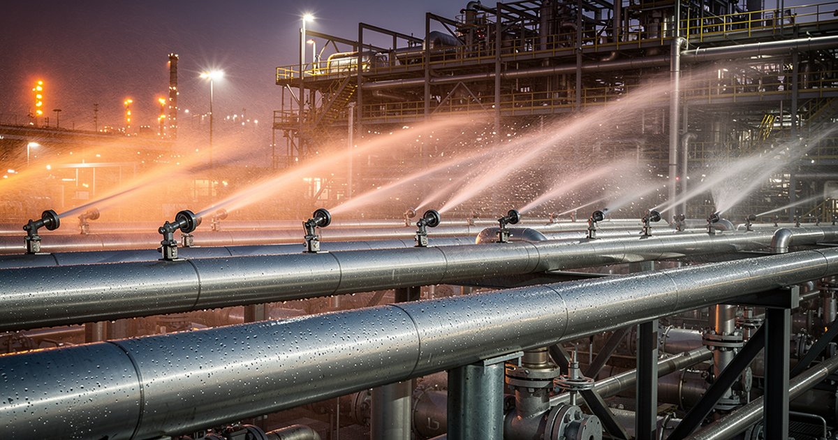
A fixed water spray system is one of the most reliable tools in industrial fire protection engineering. It is also one of the most misapplied. Facilities that install deluge systems without a rigorous hydraulic design, a proper hazard analysis, and alignment to both NFPA 15 and applicable SAES requirements end up with systems that look compliant on paper and fail in the field. This article breaks down how these systems actually work, where they are required, how they are designed, and where the engineering discipline most often breaks down.
What Fixed Water Spray Systems Are — and What They Are Not
NFPA 15, Standard for Water Spray Fixed Systems for Fire Protection, defines a fixed water spray system as a special system of piping connected to a water supply and equipped with open spray nozzles arranged to discharge water in a predetermined pattern over a designated area. The critical distinction from a standard sprinkler system is this: there are no fusible links or heat-sensitive elements at the nozzle. The nozzles are open. When the system activates — via a deluge valve triggered by detection — every nozzle in the zone discharges simultaneously.
That design characteristic makes fixed water spray systems exceptionally well-suited for industrial hazards where rapid, total-area wetting is the engineering objective. The three primary protection strategies are:
- Extinguishment — direct application to a burning surface to knock down and suppress combustion.
- Exposure protection — wetting adjacent equipment, vessels, or structural steel to limit heat absorption and prevent thermal failure or BLEVE (boiling liquid expanding vapor explosion).
- Prevention — continuous wetting of a surface where flammable liquid might be released, preventing ignition before a fire starts.
Confusing these three objectives is the first place designs go wrong. A system engineered for exposure protection has different density, nozzle type, and hydraulic assumptions than one engineered for extinguishment. NFPA 15 treats them distinctly, and so must the design engineer.
Where NFPA 15 Systems Are Required in Saudi Industrial Facilities
In Saudi Aramco facilities, fixed water spray systems appear most frequently under SAES-B-017 (Fire Water System Design) and project-specific engineering standards that reference NFPA 15 as the baseline design document. Common mandatory applications include:
- LPG spheres and bullets — exposure protection against jet fire impingement and pool fire radiation. The design criteria typically require wetting of the entire vessel surface at a minimum application rate, often combined with a cooling water ring design.
- Transformer protection — electrical substations containing large oil-filled power transformers require deluge systems capable of rapid response and defined application densities to prevent fire spread between units.
- Flammable liquid pumps and pump pads — process pumps handling hydrocarbons at elevated temperatures or pressures are common ignition sources. Spray systems provide both suppression and cooling capability.
- Loading and unloading racks — truck and rail loading facilities handling flammable liquids require fixed spray coverage aligned with drainage and containment design.
- Process equipment in high-consequence areas — reactors, heat exchangers, and separators in close proximity where fire in one unit can rapidly escalate to adjacent equipment.
The SAES framework does not always specify the application rate directly for every scenario. It often references NFPA 15 tables and requires the design engineer to justify the selected density through a hazard analysis. That delegation of judgment to the engineer is not a gap — it is a professional expectation. Treating it as ambiguity that can be resolved by picking the lowest number in the table is where compliance risk enters the picture.
The Hydraulic Design Requirement: Where Most Systems Underperform
The defining engineering task in an NFPA 15 system design is the hydraulic calculation. Unlike a prescriptive pipe schedule for a small sprinkler system, fixed water spray systems require a complete hydraulic model because the operating characteristics of open nozzles across a large, simultaneously-active zone create significant pressure variation along the pipe network.
The core parameters the design must solve:
- Nozzle selection and K-factor — Different spray nozzle types (directional, open orifice, deflector-style) produce different spray patterns, droplet sizes, and flow rates at a given pressure. The K-factor — the flow coefficient expressed as flow rate per square root of pressure — must match the hazard and protection objective. A nozzle selected for wide-angle deflection exposure protection will not perform the same as a directional impingement nozzle on a vessel surface.
- Minimum operating pressure — NFPA 15 requires that every nozzle in the design area operate at or above its minimum design pressure simultaneously. The hydraulic calculation must confirm this for the most hydraulically remote nozzle, not just the closest.
- Application density — expressed as gallons per minute per square foot (gpm/ft²) or liters per minute per square meter (lpm/m²), the required density is a function of hazard type and protection objective. NFPA 15 provides minimum densities for common hazards, but these are floors, not ceilings — the hazard analysis may justify higher densities.
- Water supply demand and duration — total flow demand across all simultaneously-activated zones must be validated against the available fire water supply, including the impact of simultaneous hose stream demand per SAES requirements. System duration is typically a minimum of 30 minutes for most industrial applications, though specific hazard scenarios may require more.
Hydraulic calculation errors — incorrect pipe friction loss factors, missed minor losses at fittings, or failure to account for elevation differences — can result in a system that appears to meet design on paper but delivers inadequate pressure and density at the nozzles during an actual event. Field commissioning and acceptance testing per NFPA 15 Chapter 8 must validate calculated performance, not simply confirm that water flows.
Nozzle Placement: The Engineering Logic Behind Coverage
Spray nozzle placement is not an aesthetic exercise. Every nozzle position must be justified by coverage area, trajectory, and the geometry of the hazard being protected. NFPA 15 requires that the designer demonstrate complete wetting of all protected surfaces — no gaps, no shadowing from structural members or equipment, no areas that remain dry during discharge.
Common placement failures seen in field inspections:
- Nozzles positioned to wet open air rather than vessel surfaces, because the design was transposed from a previous project without adjusting to the actual equipment geometry.
- Nozzle headers that create shadowing — a pipe or structural beam intercepts the spray cone before it reaches the target surface.
- Insufficient nozzle density on the underside of horizontal vessels, which is where jet fire impingement typically occurs first and where wetting is hardest to achieve with top-mounted headers.
- Failure to account for wind effects in outdoor installations, which can deflect spray patterns enough to compromise coverage in the prevailing wind direction.
These are not marginal concerns. A vessel that is 80% wetted during a pool fire is not meaningfully safer than one that is unprotected — the unprotected area becomes the failure point. The design must achieve complete coverage under the specified discharge conditions.
Testing, Inspection, and the Maintenance Gap
NFPA 25, the standard for inspection, testing, and maintenance of water-based fire protection systems, governs the ongoing operability of fixed water spray systems after installation. For Saudi facilities, SAES-B-017 and project-specific maintenance plans layer additional requirements on top of NFPA 25 minimums.
The most common maintenance failure in fixed water spray systems is nozzle obstruction. Open nozzles are exposed to the process environment — dust, corrosive atmospheres, hydrocarbon deposits, and biological fouling in warm climates can partially or fully block nozzles over time. An annual flow test that simply confirms the deluge valve opens does not verify that individual nozzles are delivering the designed flow and pattern.
Full-pattern acceptance testing — activating the system and confirming nozzle discharge across the entire protected area — should be conducted at commissioning and at intervals defined in the maintenance plan. In Saudi Arabia’s desert environment, nozzle orifice fouling timelines can be significantly shorter than in temperate climates, which means maintenance intervals appropriate for a European refinery may not be conservative enough for a facility operating in the Rub’ al Khali.
Detection system integration is equally critical. A fixed water spray system is only as fast as the detector that activates it. Detection response time, detector placement relative to the hazard, and the logic between detection signal and deluge valve actuation must be verified as a system — not as individual components in isolation.
The Bottom Line
Fixed water spray systems are not passive infrastructure. They are active engineering systems with hydraulic performance requirements, nozzle placement criteria, detection integration dependencies, and maintenance obligations that must all be executed correctly for the system to perform its function when it matters. NFPA 15 provides the engineering framework. SAES requirements define the project baseline. The design engineer’s job is to close the gap between a compliant drawing set and a system that actually delivers the required density to the right surface at the right pressure — on the first discharge, in real conditions, without warning. That is the standard. Everything else is paperwork.
Work With Ignis Sentinel Engineering
Need a fire risk assessment, a third-party plan review, or an NFPA/SAES
compliance check for your facility? Our engineers help Saudi and international
industrial operators design safer operations.