

HiltonC
A facility can have every suppression system on the approved list — deluge, foam, sprinklers, hose reels — and still run out of water in the first twenty minutes of a serious fire. That is not a hypothetical. It is what happens when firewater storage and distribution are treated as a procurement exercise rather than an engineering one. The reservoir gets sized to a rough rule of thumb, the ring main gets routed around structural obstacles, and the hydraulic model never accounts for simultaneous demand from more than one hazard area. When a real fire scenario develops, the system delivers pressure at the nearest hydrant and almost nothing at the one that actually matters.
Getting firewater supply right means working backwards from the worst credible fire scenario — not forward from a catalogue specification. This article covers how to engineer firewater storage capacity, ring main hydraulics, and distribution architecture to meet NFPA 22, NFPA 24, and Saudi Aramco SAES requirements for industrial process facilities.
Start With Demand, Not Volume
The single most common error in firewater system design is sizing the storage reservoir before completing the demand analysis. Volume is a result, not a starting point. Before you can specify a tank, you need answers to three questions: what is the design fire scenario, what systems activate simultaneously, and for how long must the supply be sustained?
NFPA 22, which governs water storage tanks for fire protection, does not prescribe a volume. It establishes the engineering basis for calculating required flow and duration — and that basis varies significantly by hazard type, occupancy classification, and supplemental system interaction. A large-diameter fixed-roof hydrocarbon tank protected by a foam-water deluge system and supplemented by monitor nozzles will generate a simultaneous demand profile that is fundamentally different from an industrial warehouse with an ESFR sprinkler system. Both are valid NFPA 22 applications. Neither can be sized from a general rule.
For Saudi Aramco facilities, SAES requirements add another layer: Aramco engineering standards specify minimum firewater flow rates and durations for specific facility classifications, and those numbers must be reconciled with NFPA demand calculations when both apply. Where the two frameworks diverge, the more conservative requirement governs. Engineers who assume the frameworks will always agree — or who apply only one — create compliance gaps that surface during third-party review or Saudi Civil Defense inspection.
The output of a proper demand analysis is a simultaneous demand matrix: a structured summary of which systems activate together under the design fire scenario, what flow rate each requires, and the total duration the supply must sustain without replenishment. That matrix drives every downstream decision — storage volume, pump selection, distribution sizing, and the zoning strategy for the ring main.
Storage Configuration: More Than a Tank
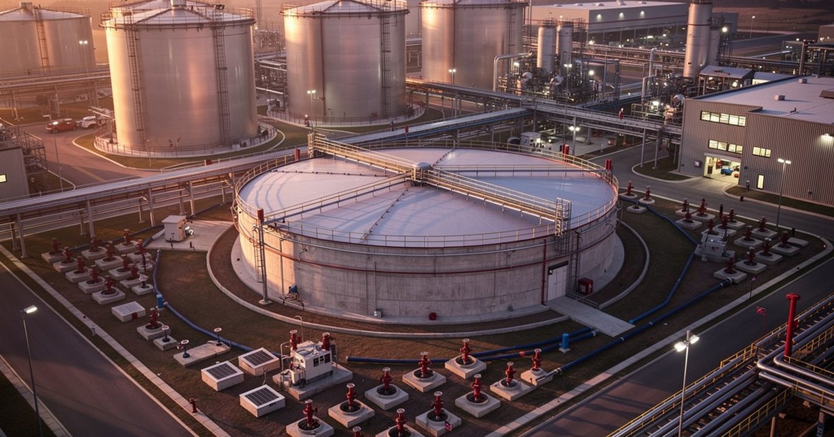
Once the demand matrix is complete, storage configuration becomes an engineering decision with real consequences. The fundamental choice is between a single large reservoir and distributed storage — suction tanks, atmospheric storage tanks, gravity-fed elevated tanks, or a combination. Each configuration carries different implications for reliability, maintenance access, seismic risk, freeze protection, and the hydraulic head available to the pump suction.
NFPA 22 addresses tank types in detail: ground-level steel tanks, suction tanks, pressure tanks, embankment-supported coated-fabric tanks, and wooden tanks each have specific structural, inspection, and operational requirements. For most Saudi industrial applications, ground-level steel tanks with cathodic protection are the standard, but the selection must be justified against site conditions — not defaulted to because it is familiar.
Redundancy is a non-negotiable design principle for any firewater storage system serving a high-consequence process facility. A single tank with a single inlet and a single suction line is not a reliable firewater supply; it is a single point of failure. Minimum credible design includes isolation valve arrangements that allow one tank to be taken out of service for inspection or repair without compromising the available supply from remaining storage. Where the facility risk profile warrants it, active replenishment from a municipal or utility source — sized and valved so that it supplements rather than replaces stored supply — adds another layer of resilience.
Storage tank siting is equally important. Tanks must be located so that suction piping runs are kept as short and straight as practical, minimising friction losses between storage and the pump suction header. They must be outside the credible fire zone of the hazards they protect — a firewater tank positioned inside a tank farm bund serves no one. And they must be accessible for inspection, maintenance, and emergency replenishment under operational conditions.
Ring Main Hydraulics: Where the Engineering Gets Specific
The firewater ring main — the looped distribution network that carries supply from the pump station to yard hydrants, system connections, and monitor nozzle stations — is where most hydraulic failures originate. A ring main that looks adequate on a pipe routing diagram can be chronically pressure-deficient under simultaneous demand if the hydraulic model is not built correctly.
NFPA 24, which governs underground fire protection mains and their appurtenances, establishes the engineering basis for buried ring main design: pipe material selection and burial depth, joint standards, valve spacing and accessibility, and the hydrostatic and flow test requirements that must be met before a system is accepted. For Saudi applications, SAES standards add requirements around burial depth relative to utility corridors, valve chamber construction, and traceability of materials to approved manufacturer lists.
The hydraulic model for a ring main must be developed using pipe flow simulation software that accounts for actual pipe material and age (including expected C-factor degradation over system life), all tee and branch connections, valve positions under normal operation, and the simultaneous demand imposed at multiple nodes under the design fire scenario. A model that only simulates single-point demand will always appear to pass. The meaningful test is multi-point simultaneous demand — two hydrants open, a deluge system active, and monitor nozzles flowing at the far end of the ring.
Loop sizing is driven by that multi-point scenario. Where a single pipe diameter cannot maintain the required residual pressure at all critical nodes under simultaneous demand, the solution is either a larger main diameter, additional looping, or strategically placed booster capability. Engineers who skip the simultaneous demand scenario during design reliably discover the shortfall during acceptance testing — at a stage where re-engineering the buried ring main is expensive and schedule-critical.
Pump Station Integration and Zoning Strategy
The firewater pump station — governed by NFPA 20 — must be hydraulically matched to the ring main it feeds. The pump curve must intersect the system curve at the design operating point, with enough margin that the system delivers the required residual pressure at the most hydraulically remote demand node under the simultaneous demand scenario. Oversized pumps that generate excessive pressure at low-demand nodes can cause their own problems: water hammer, valve damage, and flow control difficulties at hose connections.
Zoning strategy determines how the ring main is divided into controllable sections. Properly engineered zoning allows operators to isolate a segment for maintenance or emergency repair without taking the entire ring out of service. It also allows the system to be configured so that a single valve failure cannot deprive a critical hazard area of firewater supply. The zoning design should be documented in a system schematic that is kept current as the facility evolves — because facilities change, and firewater systems that were correctly zoned at commissioning can become inadequate after years of process modifications and facility expansion that no one mapped back to the fire protection design basis.
Acceptance Testing and Ongoing Verification
A firewater storage and distribution system is not validated by the hydraulic model. It is validated by flow testing that demonstrates the installed system actually delivers the design flow and pressure at the points required under conditions that simulate the design fire scenario. NFPA 24 prescribes the hydrostatic and flow test methodology for underground mains. NFPA 25 establishes the ongoing inspection, testing, and maintenance program that keeps the system verified throughout its operational life.
For Saudi Aramco facilities, periodic system testing is not optional or left to operator discretion — it is a compliance requirement with defined frequencies and documentation standards. Operators who cannot produce current test records during a Saudi Civil Defense inspection face compliance findings that can trigger operational restrictions.
The most important thing to understand about firewater system verification is that it degrades over time without a deliberate maintenance program. Buried pipe accumulates tuberculation. Valves seize. Strainers blind. Hydrant outlets corrode. A system that passed acceptance testing at commissioning may be delivering meaningfully less flow a decade later if no one has been systematically testing and maintaining it. NFPA 25 is the framework for preventing that degradation from becoming invisible — and from becoming lethal.
The Bottom Line
Firewater storage and distribution is the foundation every other fire suppression system depends on. Deluge systems, foam systems, and sprinkler networks all perform to specification only if the supply behind them is there when the demand appears. Engineering that supply correctly — from simultaneous demand analysis through storage configuration, ring main hydraulics, pump station integration, and acceptance testing — is not overhead. It is the reason the other systems work.
Facilities that treat firewater storage as a commodity decision and ring main routing as a drafting exercise will eventually discover the gap. The question is whether they discover it during a flow test or during a fire.
Work With Ignis Sentinel Engineering
Need a fire risk assessment, a third-party plan review, or an NFPA/SAES
compliance check for your facility? Our engineers help Saudi and international
industrial operators design safer operations.