

HiltonC
A sprinkler system that activates. A foam deluge that triggers. A hose station that charges. Every active fire suppression component in an industrial facility depends entirely on one thing working correctly before any of it matters: the fire water supply system. Design that system inadequately, and everything downstream fails at the worst possible moment.
Fire water supply engineering is one of the most consequential disciplines in industrial fire protection — and one of the most frequently underengineered. For Saudi industrial operators, where facilities often serve high-hazard processes and fall under overlapping NFPA and SAES requirements, getting the supply side right isn’t optional. It’s the foundation the rest of your fire protection system is built on.
What Fire Water Supply Engineering Actually Covers
Fire water supply encompasses everything from the water source through to the point of discharge at suppression equipment. That includes storage tanks, fire pumps, private fire mains, hydrants, hose stations, and the hydraulic design logic that ties all of it together. It is governed primarily by a cluster of NFPA standards:
- NFPA 22 — Water Tanks for Private Fire Protection: sizing, construction, and maintenance of above-ground and underground storage tanks.
- NFPA 24 — Installation of Private Fire Service Mains and Their Appurtenances: underground and aboveground private fire mains, hydrants, and connections.
- NFPA 20 — Installation of Stationary Pumps for Fire Protection: fire pump selection, driver requirements, performance curves, and listing requirements.
In Saudi Aramco and SAES-governed projects, these NFPA standards are typically adopted by reference, with project-specific SAES requirements layered on top — particularly for minimum storage capacity, ring main configurations, and pump redundancy. The engineer’s job is to satisfy both simultaneously, resolving conflicts where they exist.
Storage: Sizing to Meet Peak Demand, Not Average Demand
The single most common failure in fire water supply design is undersizing storage capacity. Engineers calculate demand based on the highest-demand suppression scenario — the design fire — and then size storage to sustain that demand for the required duration. For most industrial and petrochemical applications, that duration is a minimum of two hours under NFPA guidance, though specific hazard classifications and authority requirements may push that to four hours or longer.
The calculation is not simply flow rate multiplied by time. It must account for concurrent demands: if a major fire in one area triggers deluge systems, hose streams, and cooling water for adjacent vessels simultaneously, the system must supply all of it without pressure dropping below minimum thresholds at any outlet. This is a peak demand calculation, and it must be stress-tested across multiple credible scenarios before tank sizing is finalized.
NFPA 22 also governs tank construction materials, fill rates, freeze protection (less relevant in Saudi conditions but relevant for other international projects), and the inlet/outlet configurations needed to ensure water remains usable — including venting and overflow provisions that are often overlooked during design review.
Fire Pumps: Reliability Over Rated Capacity
A fire pump’s job is to maintain adequate pressure and flow at every point in the fire water distribution system under simultaneous demand conditions. NFPA 20 specifies detailed requirements for pump selection, including the performance curve characteristics that ensure the pump operates stably across its range — not just at rated flow.
Industrial applications demand redundancy. For most high-hazard facilities, a single pump is not acceptable: the design should include a minimum of one duty pump and one full-capacity standby, with automatic start-up on pressure drop. For facilities where fire suppression is truly life-critical, diesel-driven standby pumps provide independence from electrical supply disruptions — a meaningful consideration in any facility where grid reliability during a major incident cannot be guaranteed.
Several issues recur in pump installations that warrant specific attention during design and commissioning:
- Suction conditions: A pump can only develop as much pressure as its suction head allows. Net positive suction head available (NPSHA) must be calculated at minimum tank level, not average, to ensure cavitation does not occur during extended fire events.
- Weekly test circulation: NFPA 25 requires fire pumps to be churn-tested weekly and flow-tested annually. Designs that don’t include an integral test header and metered flow loop make this compliance requirement difficult and therefore chronically skipped.
- Pressure relief: Pumps operating at churn (zero flow) develop maximum pressure, which can damage piping systems not rated for it. Pressure relief valves sized per NFPA 20 are not optional.
Private Fire Mains: The Backbone No One Sees
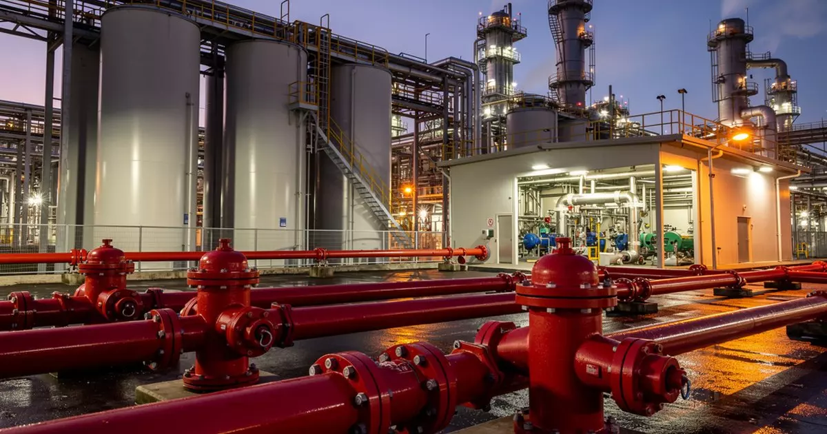
The private fire main is the underground or aboveground piping network that distributes water from storage and pumps to hydrants, hose houses, monitor nozzles, and system risers across a facility. For large industrial campuses, this is a ring main — a looped configuration that provides two-directional flow to any point and ensures that a single pipe break does not take a hydrant zone out of service.
NFPA 24 governs the design, material selection, installation, and testing of these systems. Key engineering decisions include:
- Pipe material and lining: Ductile iron with cement-mortar lining is the standard for underground fire mains in most industrial applications. Corrosion protection — both external coating and cathodic protection — is essential in aggressive soil conditions common to many Saudi industrial sites near coastal or sabkha terrain.
- Valve placement: Isolation valves must be spaced so that any single section of the ring main can be shut for maintenance or repair without disabling more than one hydrant zone. NFPA 24 specifies maximum allowable distance between valves.
- Thrust restraint: Fittings, tees, and bends are subject to significant unbalanced hydraulic thrust under flow and pressure. Concrete thrust blocks or mechanical restraint systems must be sized from hydraulic calculations — not from standard block dimensions pulled off a detail sheet.
- Flushing and testing: Before any fire main is placed in service, NFPA 24 requires hydrostatic pressure testing and flushing at velocities sufficient to clear construction debris. For large-diameter mains, achieving the required flushing velocity requires careful sequencing and temporary discharge control.
Hydraulic Analysis: Where Design Becomes Defensible
Hydrant placement, pipe sizing, and pump selection cannot be finalized without a hydraulic model. This is not optional documentation — it is the engineering basis for the entire system. The model calculates pressure and flow at every node in the distribution network under simultaneous demand scenarios, confirming that residual pressure at the hydraulically most remote outlet meets the minimum required for each connected suppression system.
For industrial facilities, hydraulic analysis must capture the worst-case simultaneous demand: a major fire suppression event with all adjacent cooling water and foam system demands active at the same time. Systems sized only for the largest single demand, without accounting for concurrent demands, routinely underperform during actual incidents.
The hydraulic model also determines where pressure-reducing valves are needed. In large ring main systems with significant elevation changes or long pipe runs, static pressure at some nodes will be significantly higher than at others. Suppression systems connected to high-pressure nodes need pressure regulation to stay within design parameters for system components and piping ratings.
SAES Overlay: What Saudi Aramco Projects Add
Saudi Aramco’s engineering standards impose specific requirements on top of the NFPA baseline that engineers must account for early in design, not during final review. These typically include minimum storage durations beyond NFPA defaults, specific pump redundancy ratios, ring main configuration requirements for facilities above a certain hazard threshold, and integration with the facility’s fire and gas system for automatic pump start confirmation.
Third-party plan review against SAES requirements is a standard part of the approval process for new facilities and major modifications. Engineers who treat SAES compliance as an afterthought — applying it as a checklist after the design is largely complete — consistently run into redesign cycles that could have been avoided by integrating the SAES requirements into the hydraulic model and equipment specifications from the start.
The Bottom Line
Fire water supply is not background infrastructure. It is the limiting factor on everything else your fire protection system can do. Undersized storage, inadequately redundant pumps, or a ring main that hasn’t been hydraulically validated means the foam deluge, the sprinklers, and the hose streams will all underperform — at exactly the moment when performance is non-negotiable.
For industrial operators in Saudi Arabia and internationally, the investment in rigorous fire water supply engineering — done to NFPA 20, 22, and 24 requirements with SAES requirements integrated from the start — is not a cost line. It is what ensures the rest of the money spent on fire protection actually delivers its intended result when it counts.
Work With Ignis Sentinel Engineering
Need a fire risk assessment, a third-party plan review, or an NFPA/SAES
compliance check for your facility? Our engineers help Saudi and international
industrial operators design safer operations.