

HiltonC
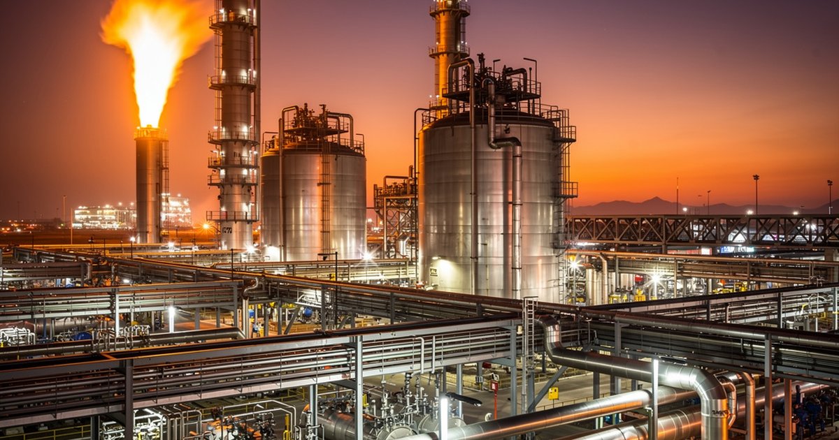
A pressure vessel engulfed in fire isn’t just a mechanical problem. It’s a countdown. Heat flux into the vessel wall raises internal pressure faster than operators can respond, and if the depressurization system wasn’t engineered correctly from the start, there’s no recovery — only consequence management after the fact. This article breaks down how fire exposure scenarios are analyzed for pressure vessels, what API 521 and SAES-D-004 require in terms of depressurization and relief, and where facilities most commonly get it wrong.
Why Fire Exposure Is a Different Design Case
Most pressure vessels are designed for their normal operating loads — internal pressure, thermal cycling, weight, and occasionally external loading. Fire exposure adds a fundamentally different condition: a time-dependent heat source acting on the vessel shell that raises both the wall temperature and the internal vapor pressure simultaneously.
The engineering challenge is that these two effects work against each other. As wall temperature rises, the yield strength of carbon steel drops — sometimes dramatically. At the same time, internal pressure is climbing because liquid inventory is vaporizing. The result is a vessel that is simultaneously weaker and more pressurized. Without adequate pressure relief and depressurization capability, this ends in one of two failure modes: a pressure burst above the vessel’s weakened allowable stress, or a catastrophic Boiling Liquid Expanding Vapor Explosion (BLEVE) if the liquid inventory is a flammable hydrocarbon.
This is not a theoretical failure mode. BLEVEs and fire-exposed vessel failures are among the highest-consequence events in the petrochemical industry. The engineering disciplines that prevent them — relief system design and emergency depressurization — are well-established, but they require deliberate application at the facility design stage.
API 521: The Engineering Basis for Relief and Depressurization
API Standard 521, Pressure-Relieving and Depressuring Systems, is the global reference document for this discipline. It establishes two complementary lines of defense: pressure relief devices (PRDs) sized for fire exposure, and emergency depressurization systems designed to reduce vessel pressure before wall integrity is compromised.
Fire case relief sizing. API 521 requires that pressure relief valves protecting vessels exposed to fire be sized to handle the maximum vapor generation rate produced by external heat input. The heat flux assumptions depend on whether the vessel has adequate drainage (wetted surface area is reduced by prompt liquid runoff) and whether approved fireproofing is applied to the vessel shell. Fireproofed vessels with good drainage receive credit for lower effective heat input; unprotected, poorly drained vessels must be sized for the full fire case flux. The standard provides heat absorption equations based on wetted surface area, and the relief valve must be large enough to vent the resulting vapor load while holding pressure at or below the vessel’s maximum allowable accumulated pressure.
Emergency depressurization. For vessels containing flammable hydrocarbons above a threshold inventory — typically characterized by a combination of volume and operating pressure — API 521 calls for an emergency depressurization system capable of reducing the vessel’s operating pressure to 50 percent of design pressure, or 100 psig (whichever is lower), within 15 minutes. This target is not arbitrary. It reflects the empirical relationship between internal pressure and the likelihood of vessel failure under fire exposure: reducing pressure to that threshold significantly extends the time window before the wall reaches critical temperature at its reduced yield strength. That time buys operators and emergency responders the opportunity to suppress the fire before vessel failure occurs.
Blowdown valve design. The depressurization rate is controlled by emergency blowdown valves, typically fail-open on loss of instrument air or control signal, discharging to a closed blowdown drum or flare header. Valve sizing must account for both the required depressurization rate and the hydraulic limitations of the relief header — you cannot size the valve in isolation from the downstream system it discharges into. API 521 provides guidance on two-phase flow considerations and header back-pressure limits that must be respected to avoid creating new hazards in the blowdown system itself.
SAES Requirements and the Saudi Aramco Context
For facilities operating within Saudi Aramco’s engineering jurisdiction, SAES-D-004 (Pressure Relief Systems) and SAES-J-600 (Safeguarding Instrumented Systems) layer Saudi Aramco-specific requirements on top of the API 521 baseline. Understanding where SAES diverges from the API standard is critical for engineers designing or reviewing systems in that operating environment.
Fireproofing credit. SAES-H-101 governs passive fireproofing for Saudi Aramco facilities, and the credit allowed for fireproofing in pressure relief calculations is conditional on meeting those passive fireproofing standards. An operator cannot simply claim the fireproofed heat flux reduction in a relief calculation without demonstrating that the fireproofing system meets SAES-H-101’s thickness, material, and inspection requirements. This linkage between passive and active fire protection engineering is one area where third-party review frequently identifies non-conformances in Saudi industrial facilities.
Depressurization automation and SIL classification. SAES-J-600 and the associated Saudi Aramco safety instrumented system requirements typically assign emergency depressurization initiation to a Safety Instrumented Function (SIF). The Safety Integrity Level (SIL) required for that function depends on the consequences of failure on demand — and for a large hydrocarbon vessel under fire exposure, SIL 2 is a common outcome of the Layer of Protection Analysis (LOPA). This means the blowdown valve, its solenoid, and the associated logic solver cannot be generic commercial components; they must meet validated SIL 2 hardware and software requirements with documented proof-test intervals.
Flare header capacity. Saudi Aramco facilities operating at refinery or gas plant scale discharge relief and blowdown flows to shared flare headers. SAES-J-002 and associated relief load studies require that the simultaneous relief load from a single-fire scenario — potentially involving multiple vessels in a process unit — does not exceed flare header and tip capacity. This is a system-level calculation, not a vessel-by-vessel exercise, and it must be updated whenever process modifications change relief loads in any section of the affected plant.
Where Facilities Get It Wrong
In third-party plan reviews and compliance assessments, the same failure patterns appear repeatedly across industrial facilities — both in the Kingdom and internationally.
- Relief valves sized for normal operation only. The fire case is a distinct overpressure scenario with its own sizing requirement. Facilities that size PRDs solely for blocked-outlet or thermal relief cases and assume those devices are adequate for fire exposure are underprotected. The fire case must be explicitly analyzed and documented.
- Fireproofing credit claimed without SAES compliance. Engineers take the reduced heat flux assumption in their relief calculation, but the installed fireproofing hasn’t been inspected or doesn’t meet thickness requirements. The two systems are linked — passive protection credit requires passive protection integrity.
- Blowdown valves sized in isolation. A valve sized to achieve the 15-minute depressurization target based on vessel volume alone may be unable to achieve that rate when back-pressure from a loaded flare header reduces the available pressure differential. Header hydraulics must be part of the sizing basis.
- Outdated relief load studies. Process modifications — new feeds, increased throughput, changed operating temperatures — alter the heat input and vapor generation rates that the relief system was originally sized for. Relief load documentation must be treated as a living engineering document, not a one-time design deliverable.
- Depressurization excluded from SIL assessment. In facilities with established Safety Instrumented Systems (SIS), emergency depressurization is sometimes omitted from the LOPA scope on the assumption that it’s a mechanical system. It isn’t — the blowdown initiation logic is a safety function and must be assessed accordingly.
The Intersection With Passive Fireproofing and Drainage
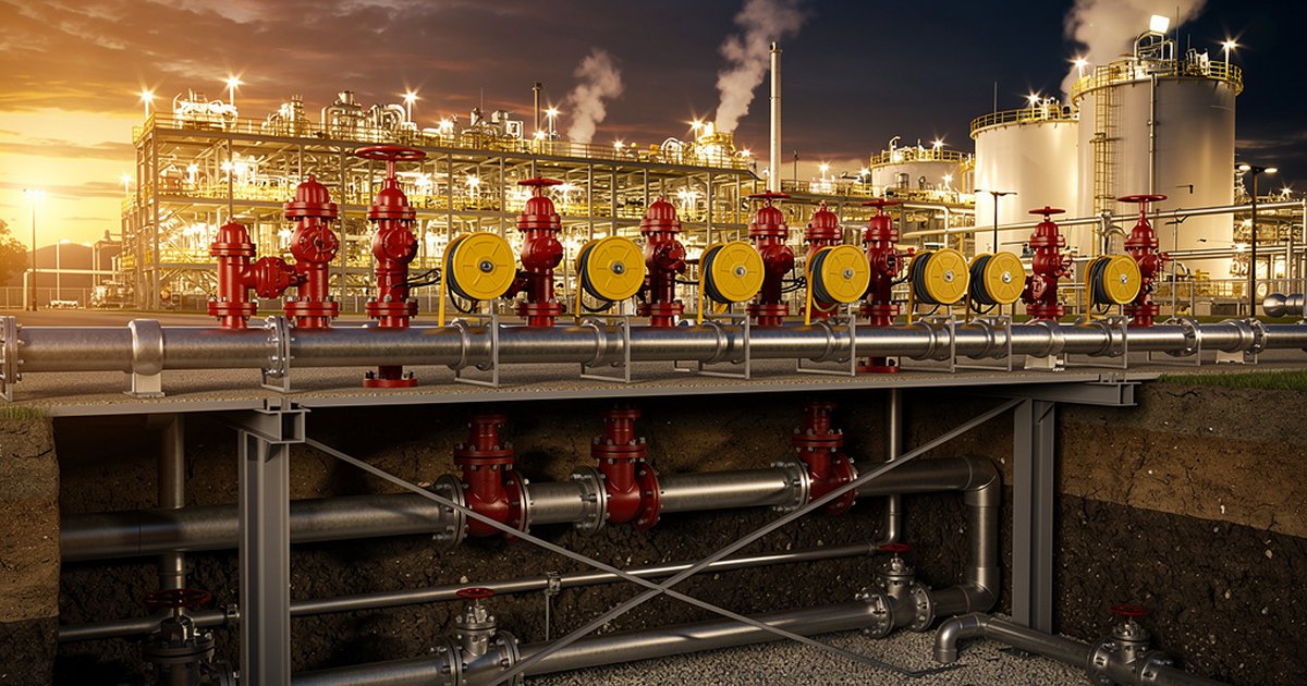
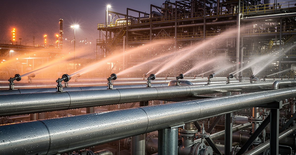
Pressure vessel fire exposure engineering doesn’t exist in isolation from the site’s broader fire protection strategy. The relationship between passive fireproofing, drainage design, and pressure relief is a system-of-systems problem. Fireproofing on vessel skirts and structural supports delays the onset of structural failure but does not cool the vessel shell directly. Drainage slopes and impoundment design affect how much burning liquid remains in contact with the vessel base, which directly determines the wetted surface area and heat input. Water deluge applied to the vessel shell from a fixed spray system (designed to NFPA 15 or SAES-A-007) can substantially reduce heat flux to the vessel — but the relief system must still be sized for the case where deluge fails or is delayed.
The correct engineering posture is defense-in-depth: drain liquid away from the vessel quickly, fireproof structural elements, apply active cooling where the risk justifies it, and size the relief and depressurization systems for the worst credible fire exposure scenario assuming other protective layers have not yet engaged. Each layer reduces consequence; none of them individually eliminates the need for the others.
The Bottom Line
Pressure vessel fire exposure and depressurization engineering is one of the highest-stakes disciplines in industrial fire protection — and one of the most frequently under-documented. API 521 provides a rigorous, well-developed technical basis. SAES requirements add specificity for Saudi operating environments. The gap between compliance on paper and actual protection in the field almost always comes down to the same factors: fire case relief not explicitly sized, passive fireproofing credit not verified, blowdown hydraulics not validated at the system level, and SIL assessments that missed the depressurization function entirely.
Getting this right at the design stage is orders of magnitude less expensive than getting it wrong in the field. The engineering is available. The standards are clear. What’s required is the discipline to apply them completely — not just to the vessel, but to the entire system it operates within.
Work With Ignis Sentinel Engineering
Need a fire risk assessment, a third-party plan review, or an NFPA/SAES
compliance check for your facility? Our engineers help Saudi and international
industrial operators design safer operations.