


HiltonC
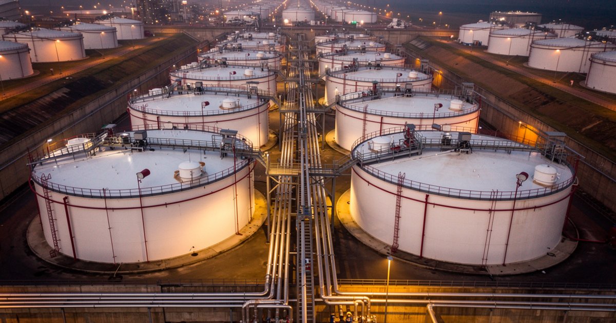
A large atmospheric storage tank fire is one of the most operationally and financially destructive events an industrial facility can experience. Boilover events in crude oil tanks, rim seal fires in floating-roof tanks, and full-surface fires in fixed-roof vessels carrying flammable liquids share a common characteristic: they escalate quickly, they demand enormous suppression resources, and they punish facilities that treated fire protection as a compliance checkbox rather than an engineering problem.
Tank farm fire protection is not complicated in concept — but it is unforgiving in execution. The margin between a system that controls a fire and a system that fails to contain it often comes down to decisions made during the design phase: foam application rates, cooling water demand calculations, detector placement, and the hydraulic performance of fixed equipment under actual fire conditions. This article covers the engineering fundamentals that operators and project engineers need to get right from the start.
Understanding the Hazard Profile Before Designing Anything
Effective tank farm fire protection begins with a clear hazard inventory, not a standard template. The relevant variables include the flash point and vapor pressure of stored products, tank type (fixed-roof, external floating-roof, internal floating-roof, or cone-roof), tank diameter and shell height, product turnover rate, and the proximity of adjacent tanks and process equipment.
These variables directly govern system design requirements. A tank storing crude oil with a flash point below 37°C presents a fundamentally different ignition and suppression challenge than one storing diesel fuel. Floating-roof tanks are particularly hazard-specific: rim seal fires — ignited by accumulated vapor between the floating deck and the tank shell — are the most statistically common tank fire type in storage facilities worldwide. They are also the most manageable if rim seal protection is properly engineered. Full-surface fires, by contrast, occur when the floating deck sinks or the roof is compromised, and they demand significantly higher foam and water resources.
NFPA 11 (Standard for Low-, Medium-, and High-Expansion Foam) and NFPA 30 (Flammable and Combustible Liquids Code) provide the core framework for this hazard characterization. Saudi Aramco engineering standards — particularly SAES-D-005 and supporting fire protection standards — layer additional requirements and, in some cases, more conservative design criteria onto these baselines. Knowing which regime applies to your facility before any design work begins is not optional; it determines the system architecture.
Fixed Foam System Design: Application Rates and Delivery Methods
Fixed foam systems are the primary suppression tool for atmospheric storage tanks holding Class I and Class II flammable liquids. The engineering core of any fixed foam system is the application rate — the volume of foam solution delivered per unit of liquid surface area per minute. NFPA 11 establishes minimum application rates based on product type, foam concentrate type, and tank configuration. These are minimums, not recommendations; facilities with high-value inventories, limited response capacity, or extended emergency response times should design above code minimum.
Delivery method selection follows hazard type. For fixed-roof tanks, sub-surface injection systems deliver foam concentrate below the product surface, allowing it to rise through the fuel and form a blanket on top. This approach avoids the problem of foam being destroyed by fire exposure during surface application, but it requires compatible foam concentrates and products — sub-surface injection is not appropriate for all fuel types, and it is incompatible with water-miscible products entirely. Surface-applied systems using top-mounted foam chambers are the alternative and remain common for products where sub-surface compatibility is uncertain.
For floating-roof tanks, the design focus shifts to the annular area between the deck and the tank shell. Foam pourers positioned at the rim feed the annular ring directly. NFPA 11 specifies minimum application rates for the annular seal area, and the hydraulic design must confirm that all pourers in a segment can be supplied simultaneously at the required rate. The pourer spacing, pipe sizing, and deluge valve configuration must all be modeled — not assumed — to confirm this performance.
Foam concentrate selection ties directly to the hazard. Aqueous film-forming foam (AFFF) has been the dominant concentrate in industrial tank farm applications for decades, though regulatory pressure on per- and polyfluoroalkyl substance (PFAS) compounds is accelerating the transition toward fluorine-free foam (F3) alternatives. The transition is not a simple product substitution: F3 concentrates can require higher application rates to achieve equivalent suppression performance, and existing system hydraulics may need to be re-evaluated to confirm adequacy. Facilities still operating AFFF systems should understand where their jurisdiction and operator (Saudi Aramco included) currently stands on this transition — and plan accordingly rather than waiting for a regulatory forcing event.
Cooling Water Demand: The Calculation Most Facilities Get Wrong
Fixed suppression addresses the burning tank. Cooling water addresses the tanks that aren’t burning — yet. Radiant heat from a large tank fire can be sufficient to ignite adjacent tanks, damage floating deck pontoons, and compromise the structural integrity of support equipment. The cooling water system exists to hold adjacent tanks below critical temperature thresholds long enough for suppression to work and for personnel to achieve safe positions.
NFPA 15 (Standard for Water Spray Fixed Systems for Fire Protection) provides the basis for exposure protection design. The calculation methodology requires identifying each tank within the exposure radius of the fire scenario, calculating the surface area requiring cooling coverage, selecting an application density appropriate for the exposure heat flux, and summing the resulting demand across all simultaneously active cooling zones.
This is where design errors concentrate. Common failures include calculating cooling demand for the on-fire tank rather than adjacent tanks, using application densities below the NFPA 15 minimums for the actual heat exposure scenario, and failing to account for the hydraulic impact of running cooling and suppression systems simultaneously. The fire water system must be sized for the worst credible simultaneous demand — not the average case. Facilities that discover during commissioning or third-party review that their fire water pump capacity is undersized for simultaneous suppression and cooling operations face an expensive retrofit problem that could have been solved at the design table.
Saudi Aramco’s fire water demand criteria, applied through its engineering standards, historically require confirmation that the facility fire water system can sustain the calculated maximum demand for an extended duration — typically two to four hours — without pump failure or tank drawdown below the minimum operating level. Independent verification of this capacity is a standard component of any credible fire protection engineering review.
Detection, Alarms, and the Early-Warning Engineering Gap
Fixed suppression systems are reactive by design — they operate after a fire is confirmed and the system is activated. Detection engineering determines how quickly that confirmation occurs and, in automatic systems, how quickly suppression begins. For tank farms, the detection architecture typically combines linear heat detection or flame detectors at the rim seal area, point-type hydrocarbon gas detectors at low-level vapor zones, and manual call points at strategic intervals along access routes and around tank bunds.
Flame detectors are preferred for open-air tank farm environments where thermal detectors would produce excessive false alarms. Optical flame detectors — UV/IR or multi-spectrum IR types — provide reliable detection in environments with high ambient heat and solar radiation, provided they are positioned with unobstructed sight lines to the protected area. Coverage mapping for flame detectors in a tank farm is a geometry and siting exercise; it must be done with actual detector specifications, not assumed coverage radii.
Gas detection at the rim seal and in the bund area provides the pre-ignition warning layer. Detecting flammable vapor concentration at 20–25% of the lower explosive limit (LEL) gives operators time to investigate and respond before ignition occurs. This is particularly important for facilities where product transfer operations create routine vapor release events — distinguishing between normal operational vapor and an evolving release event requires detectors placed and calibrated with an understanding of the normal vapor environment.
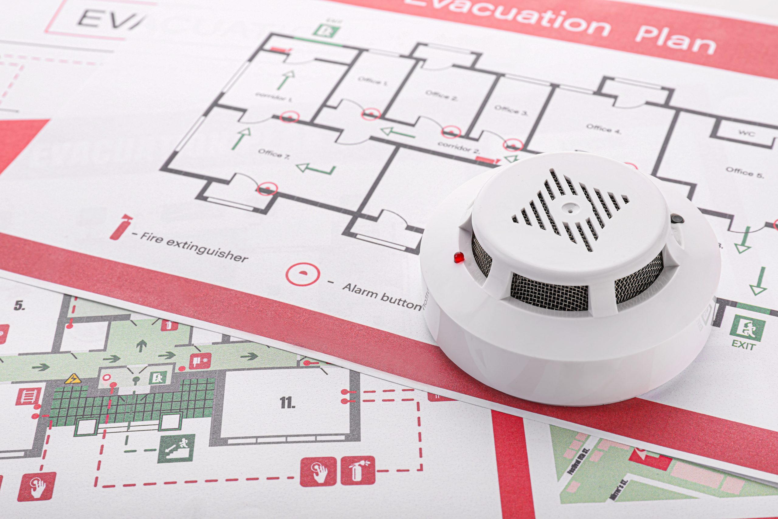
Detection system design documentation — cause-and-effect matrices, detector placement drawings, and alarm logic descriptions — must be consistent with the suppression system activation philosophy. If the design intent is automatic deluge valve operation on confirmed fire detection, the detection and suppression documentation must describe exactly which detector combinations trigger which valve responses, and that logic must be verified during commissioning. Mismatches between the design intent and the as-commissioned logic are a documented failure mode in industrial facility fire investigations.
Spacing, Drainage, and the Physical Layout of Defensible Protection
The most technically sound suppression and cooling system will underperform if the physical layout of the tank farm creates obstacles to effective application. NFPA 30 and SAES standards both establish minimum inter-tank spacing requirements that serve a dual purpose: limiting heat transfer between adjacent tanks under fire conditions, and ensuring that fixed equipment can reach its design coverage areas without obstruction.
Bund (containment dike) design is equally critical. Bunds must be sized to contain the largest single tank volume plus applicable freeboard, graded to drain away from tanks toward a remote impoundment point, and constructed of materials that will not deteriorate under prolonged hydrocarbon exposure. A bund that pools liquid beneath or adjacent to tanks under normal operational spill conditions creates the exact hazard the containment system is supposed to manage.
Drainage routing from the tank bund must not allow spilled product to migrate toward process areas, electrical infrastructure, or drainage systems that discharge to a public waterway. The fire water runoff generated during a suppression event — which can be significant — must also be routed to a containment system designed to hold contaminated water for treatment or disposal. Facilities that lack adequate capacity for contaminated fire water runoff face both an environmental compliance problem and a suppression limitation, since operational drainage constraints can limit the volume of fire water that can be applied.
The Bottom Line
Tank farm fire protection engineering is a system-level problem. Foam application rates, cooling water demand, detection architecture, and physical layout each have their own design requirements — but they interact, and the weakest element determines the system’s actual performance under fire conditions. Facilities that treat these components as independent checkboxes rather than an integrated design will discover the gaps under conditions that don’t allow for revision.
The engineering investment required to get tank farm fire protection right at the design stage is a fraction of the cost of a suppression failure. That comparison only looks favorable, however, if the design work is done by engineers who understand how these systems perform together — not just what the code minimums require of each individual component.
Work With Ignis Sentinel Engineering
Need a fire risk assessment, a third-party plan review, or an NFPA/SAES
compliance check for your facility? Our engineers help Saudi and international
industrial operators design safer operations.