

HiltonC
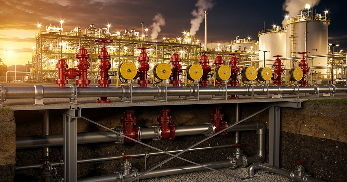
A fire hydrant is the most visible piece of fire protection infrastructure on any industrial site. It is also one of the most frequently under-engineered. Operators see the red standpipe, assume the system works, and move on. Fire protection engineers know better — because when the first responder opens that valve under real fire conditions, the hydraulic math that was never done becomes very visible, very fast.
Yard hydrant and hose reel systems are the first line of manual firefighting response for industrial facilities. They are the interface between your passive infrastructure and the people actually fighting the fire. Getting the design wrong does not just mean a failed inspection — it means inadequate flow rates, insufficient coverage, and a fire that gains ground while responders are pulling hose to reach a hydrant that should have been closer.
This article walks through the engineering fundamentals: what NFPA 24 and NFPA 291 require, how Saudi Aramco’s SAES standards layer on top, where most designs fall short, and what a properly engineered yard fire protection system actually looks like.
The Governing Standards Framework
For industrial facilities operating under international codes, yard hydrant systems are primarily governed by NFPA 24: Standard for the Installation of Private Fire Service Mains and Their Appurtenances. NFPA 24 covers the underground and above-grade piping that feeds hydrants, hose connections, and hose reel stations — from the point of connection to the public main or private water supply through to the hydrant outlet itself.
Companion standard NFPA 291: Recommended Practice for Fire Flow Testing and Marking of Hydrants governs the testing and flow-marking protocols that confirm the system delivers what the design promised. It is not enough to size the system on paper — NFPA 291 flow testing is how you prove the installed network actually performs to its rated capacity under demand conditions.
For Saudi Aramco facilities and contractors operating within the Kingdom, SAES-F-001 (Fire Protection Requirements for Onshore Facilities) establishes the baseline design criteria for yard fire protection systems. Where SAES-F-001 references or adopts NFPA provisions, those provisions carry the same mandatory weight as the SAES standard itself. Where SAES-F-001 is more stringent — and it frequently is, particularly on spacing, pressure minimums, and water supply duration — SAES governs.
Saudi Civil Defense requirements add a third layer for non-Aramco facilities: systems must meet the authority-having-jurisdiction (AHJ) requirements as interpreted locally, which in practice means demonstrating NFPA compliance with documentation sufficient to satisfy Civil Defense inspectors. The engineering basis must be on record and defensible.
Hydrant Placement: Spacing Is Not a Preference
The single most common design deficiency in industrial yard fire protection is hydrant spacing that prioritizes aesthetics or cost over coverage. NFPA 24 establishes maximum spacing and hose-reach criteria that are engineering minimums, not targets to trade against.
For industrial occupancies, the general principle is that every point in a facility should be reachable by a single hose lay from the nearest hydrant — typically with 150 feet (approximately 45 meters) of hose providing a practical working reach. But hose reach is only part of the calculation. The actual coverage radius depends on the fire scenario: a hose stream fighting a flammable-liquid pool fire on open grade needs direct access without obstructions, process equipment in the way, or hose that must be routed around pipe racks and structures.
For Saudi Aramco facilities under SAES-F-001, hydrant spacing in process areas is more prescriptive, with maximum spacing between hydrants defined based on area classification and hazard type. High-hazard process areas typically require tighter spacing than general storage or utility areas. The engineering deliverable is a hydrant coverage plot overlaid on the facility plot plan — every point in the hazardous area demonstrated to be within hose reach of at least one hydrant, with a second hydrant reachable for backup supply without moving the first hose connection.
Hydrant location relative to the hazard matters as much as spacing. Hydrants placed too close to process equipment become inaccessible when that equipment is on fire. The general rule of thumb is a minimum standoff of 40 feet (12 meters) from the hazard being protected — far enough to remain accessible under a developing fire scenario, close enough to provide effective hose stream reach without excessive pressure drop across a long lay.
Hydraulic Sizing: Where Paper Designs Fail in Practice
Hydrant spacing defines where the connection points are. Hydraulic sizing determines whether anything useful comes out of them.
NFPA 24 requires the fire service main system to be hydraulically calculated to deliver the required flow at the most hydraulically remote hydrant, at a residual pressure sufficient to support fire department operations. For industrial facilities, minimum residual pressure at the hydrant outlet is typically 20 psi (138 kPa) under full design flow — though many industrial owners and Saudi Aramco SAES requirements specify higher minimums, particularly where fire department pumpers will not augment the supply.
The design flow demand must account for simultaneous use. Industrial fire scenarios rarely involve a single hydrant in isolation. The hydraulic design must model the worst-case simultaneous demand: the number of hose streams expected to be operating at the same time, from hydrants that place the greatest combined hydraulic burden on the underground main. For large process facilities and tank farms, this simultaneous demand calculation often drives main sizing to 10-inch or 12-inch diameter underground pipe — significantly larger than what a naive sequential design might produce.
Pipe material, joint type, age, and internal condition all affect actual hydraulic performance. NFPA 24 specifies listed materials for fire service mains, and the Hazen-Williams roughness coefficients used in hydraulic calculations must reflect the installed condition, not idealized new-pipe values. Corrosion, tuberculation in older carbon steel mains, and sedimentation in infrequently flushed dead-end runs all degrade flow capacity over time. This is why periodic flow testing per NFPA 291 is not optional — it is the only way to confirm the system still delivers design intent after years of service.
Hose Reel Stations: Engineering the Last Meter
Hose reel stations are often treated as catalog selections rather than engineered components. They are not. The hose reel is the terminal point of the entire yard water supply system — and a poorly selected or poorly located hose reel can negate everything the underground infrastructure provides.
For industrial facilities, hose reel stations must be specified with hose diameter, length, and nozzle type matched to the anticipated fire scenario. A 25mm (1-inch) hose reel is appropriate for incipient-stage response in lower-hazard occupancies. For process areas with flammable liquid exposure, 38mm (1.5-inch) or larger hose with a variable-pattern nozzle — capable of switching between straight stream and wide-angle fog — provides the flow rate and pattern flexibility needed for effective suppression and crew protection.
Hose reel enclosure protection matters in Saudi conditions specifically. Ambient temperatures in process areas can reach levels that degrade hose material, deform plastic nozzle components, and — critically — cause pressure buildup in pressurized hose reels that creates hazards during access. SAES standards and local climate conditions argue strongly for shaded, ventilated enclosures and hose materials rated for high-temperature environments. UV degradation of rubber hose is a real inspection finding in Kingdom facilities; it is also completely preventable with proper specification.
Location of hose reel stations should follow the same logic as hydrant placement: accessible under fire conditions, positioned to allow hose deployment without crossing the fire zone, and mounted at ergonomic heights that allow rapid single-person deployment without mechanical assistance.
Underground Main Design: What Gets Buried Matters Most
The underground fire service main is the backbone of the yard system, and it is the one component that is most expensive and disruptive to correct after construction. Getting it right at the engineering phase — before the trenches are backfilled — is the only cost-effective approach.
NFPA 24 governs installation: pipe depth and cover requirements, thrust block sizing at bends and tees, valve spacing for isolation, and post-installation testing requirements including hydrostatic pressure testing and flush volumes before the system is placed in service. For Saudi facilities, corrosion protection — cathodic protection for metallic pipe, or the selection of non-metallic pipe where soil conditions warrant — is not a value-engineering option. Chloride-rich soils in coastal and industrial zones in the Kingdom accelerate external corrosion on unprotected steel at rates that can compromise structural integrity within years, not decades.
The ring main configuration — a looped underground network that feeds hydrants from two directions — is the preferred arrangement for process facilities precisely because it provides redundancy. If one section of main requires isolation for repair, the loop continues to supply the remainder of the hydrant network. Dead-end runs should be minimized; where they exist, manual flushing connections are required to prevent sediment accumulation and to maintain water quality.
Control valve placement governs how much of the system must be taken offline for any given repair. The valve strategy should be engineered to allow isolation of individual sections without removing fire protection from large areas simultaneously — particularly critical for continuously operating process facilities where planned shutdowns are scheduled months in advance.
The Bottom Line
Yard hydrant and hose reel systems look simple. They are not. Behind every red standpipe is an engineering basis that determines whether that connection point can actually support a firefighting operation under real demand — or whether it delivers disappointing flow at the moment it matters most.
The engineering fundamentals are clear: spacing based on hose-reach coverage analysis, hydraulic sizing that accounts for simultaneous demand at the most remote points, underground mains designed for long-term durability in the operating environment, and hose reel specifications matched to actual fire scenarios. NFPA 24 and NFPA 291 provide the framework; SAES-F-001 tightens the requirements for Saudi industrial operators specifically.
Where these systems fail, it is almost always because the engineering was treated as a procurement exercise rather than a design discipline. A hydraulic calculation that has never been verified by a flow test, a hydrant spacing layout that was never checked against a coverage plot, a hose reel selected from a catalog without regard for the fire scenario it is supposed to address — these are not hypothetical failure modes. They are routine findings on site assessments of facilities that have been operating for years without a challenge.
The time to discover these gaps is during an engineering review. Not during a fire.
Work With Ignis Sentinel Engineering
Need a fire risk assessment, a third-party plan review, or an NFPA/SAES
compliance check for your facility? Our engineers help Saudi and international
industrial operators design safer operations.