

HiltonC
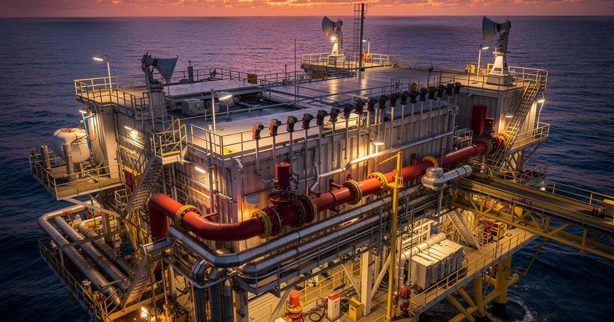
An offshore platform or floating production, storage, and offloading vessel (FPSO) concentrates hydrocarbons, high-pressure process equipment, rotating machinery, and a live-aboard crew into a structure that cannot be evacuated in minutes and cannot call the municipal fire brigade. When fire protection engineering on these facilities is treated as a collection of individual systems rather than an integrated life-safety and asset-protection architecture, the consequences are not fines or shutdowns alone — they are catastrophic and irreversible. The engineering decisions made at the design stage determine whether a fire event becomes a managed emergency or a disaster.
This is not an abstract risk profile. Offshore and FPSO facilities operate with ignition sources, flammable inventories, and confinement conditions that place them at the extreme end of industrial fire hazard. Getting fire protection right on these assets requires a different level of engineering discipline than onshore process plants — one that accounts for the marine environment, the structural limitations of a floating hull or fixed jacket, the compressed escape routes, and the regulatory frameworks that govern hydrocarbon operations at sea.
The Offshore Fire Hazard Environment Is Fundamentally Different
Onshore facilities have buffers. Distance between process units, separation from control rooms and occupied buildings, access for external emergency response — these factors meaningfully reduce consequence severity. Offshore platforms have none of them. Process equipment, living quarters, control rooms, lifeboats, and high-pressure hydrocarbon inventories are stacked within meters of each other on a structure surrounded by open water.
The fire hazard profile reflects this compression. Hydrocarbon releases on topsides can generate jet fires with radiant heat flux levels that damage structural steel in minutes and render deck access impassable before suppression systems even activate. Pool fires fed by liquid inventory can spread rapidly across grated decks, accelerated by wind that is constant and frequently strong. The marine atmosphere — salt-laden, humid, and corrosive — degrades detection hardware, suppression components, and structural fireproofing faster than equivalent onshore environments, creating a maintenance and inspection burden that must be engineered into the asset lifecycle from the beginning.
FPSO hulls introduce an additional dimension: the facility moves with sea state, which imposes dynamic loads on suppression piping, affects drainage patterns critical to foam application, and requires penetration sealing and flexible connections that fixed platforms do not need. Hull fire risks — particularly in pump rooms, cargo tanks, and void spaces — involve vapor accumulation scenarios that demand dedicated detection and suppression strategies separate from topsides protection.
Detection Architecture: Zoning, Voting Logic, and Response Time
Offshore detection design is governed by the speed at which a hydrocarbon fire scenario can escalate. Point-type heat and smoke detectors are inadequate as the primary layer in open topsides environments — wind and turbulent airflow disperse combustion products, delay activation, and generate nuisance alarms that erode operator confidence in the system. Competent offshore detection engineering uses a layered approach: open-path infrared gas detectors for continuous flammable cloud monitoring in process areas, flame detectors (UV/IR or multi-spectrum IR) for rapid positive identification of ignition, and aspirating smoke detection or beam detectors in enclosed equipment spaces and living quarters where air movement is controlled.
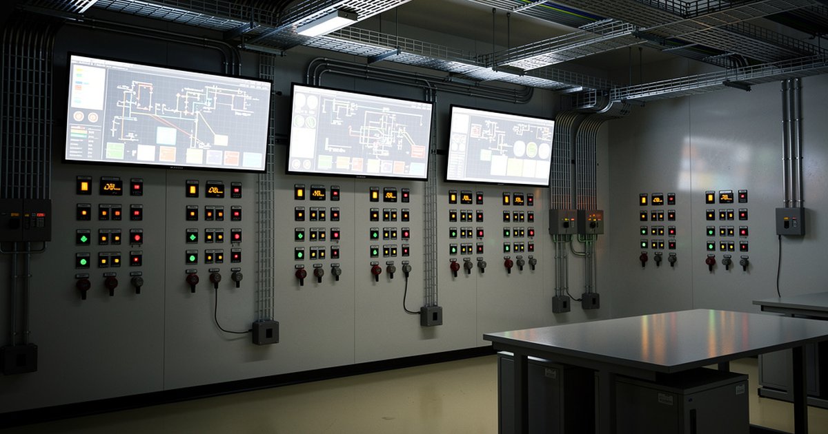
Voting logic matters. A single-detector activation in a safety-critical zone should trigger an alert; a two-out-of-two or two-out-of-three confirmation should trigger ESD and suppression release. Designing the right voting matrix requires a disciplined hazard analysis — zones with faster escalation potential warrant lower voting thresholds. Control room integration must ensure that detector status, zone identification, and response priorities are immediately clear to the operator without requiring interpretation across multiple screens or panels.
NFPA 72 provides the baseline framework for detection system design, including detector placement geometry and circuit supervision requirements. On Saudi Aramco offshore assets, SAES requirements layer on top of NFPA baselines and establish specific performance expectations for detection response and system availability. Independent verification of detector spacing, coverage overlap, and voting configuration against both frameworks is a standard deliverable of a credible engineering review — and one that is routinely absent from contractor-produced designs.
Suppression Systems: Fixed, Semi-Fixed, and Portable Layering
No single suppression technology is adequate across the full range of offshore fire scenarios. Effective protection requires a deliberate layering of fixed systems, semi-fixed systems, and portable equipment — each engineered for its specific application and integrated into the overall response sequence.
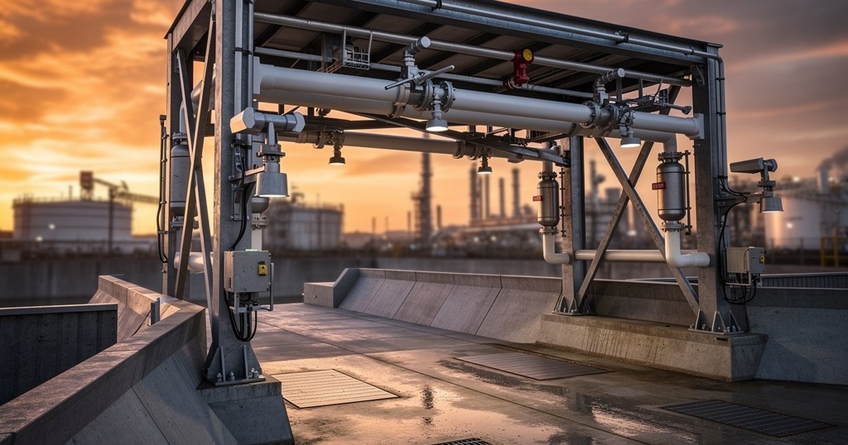
Fixed deluge systems are the primary suppression layer for topsides process areas and equipment skids where jet fire or pool fire exposure is credible. NFPA 15 governs water spray system design for these applications — application rate, nozzle selection, and hydraulic coverage must be verified against the actual heat flux levels of the design fire scenario, not generic minimums. Deluge systems protecting structural steel must be capable of maintaining surface temperature below critical thresholds throughout the fire duration; undersized systems that cool steel intermittently provide false confidence and inadequate protection.
Foam systems are required wherever liquid hydrocarbon inventory poses a pool fire risk — tank decks on FPSOs, helidecks, and areas where drainage cannot prevent liquid accumulation. NFPA 11 establishes the engineering framework for low-expansion foam application rates, solution concentrations, and system types. On FPSOs, foam system design must account for vessel motion: drainage slopes, foam application direction, and tank arrangement all affect application effectiveness. A foam system designed without understanding how the vessel sits and moves in service is a system that may not perform when it is needed.
Gaseous suppression — typically clean agents or CO₂ — is applied in enclosed spaces: switchgear rooms, battery rooms, control rooms, generator enclosures, and similar protected spaces. Room integrity is a non-negotiable prerequisite: a space that fails a door fan test will not hold agent concentration long enough to suppress a fire. Agent quantity calculation, nozzle distribution, and discharge timing must follow NFPA 2001 for clean agents and NFPA 12 for CO₂, with hold time adequate to allow safe manual intervention or system reset.
ESD Integration and the Fire and Gas System
The fire and gas (F&G) system is the nerve center of offshore fire protection — and the most frequent source of engineering failure on projects where fire protection and process safety are managed as separate workstreams. Detection events must drive ESD actions in a defined, verified sequence: HVAC shutdown to prevent gas migration into occupied spaces and control rooms, ESD valve closure to isolate hydrocarbon inventory, blowdown initiation where required to reduce pressure and inventory in the affected segment, and suppression system activation in the appropriate zone.
The cause-and-effect matrix that defines these relationships must be developed by engineers who understand both the process system and the fire protection response — not assembled by contractors working from incomplete P&IDs or generic templates. Every input-to-output path must be traced, verified in logic system configuration, and proven functional during acceptance testing. A cause-and-effect matrix that has not been walked down against the actual installed system is a document, not a protection architecture.
HVAC shutdown sequencing deserves particular attention. Offshore facilities rely on pressurized HVAC systems to maintain occupied spaces free of hydrocarbon vapor intrusion; loss of that pressurization barrier during a gas release — if HVAC shutdown is delayed, sequenced incorrectly, or bypassed — can introduce a flammable atmosphere into spaces that personnel are depending on for refuge. The interaction between the F&G system, HVAC control, and temporary refuge integrity is an engineering problem that requires dedicated analysis, not a default setting.
Structural Fireproofing and Escape Route Integrity
Passive fire protection on offshore structures serves a different function than on onshore facilities. The objective is not to contain a fire until it self-extinguishes — it is to maintain structural integrity and escape route viability long enough for personnel to reach muster stations and lifeboats. That time window is finite and asset-specific; it must be calculated, not assumed.
Structural steel in jet fire exposure zones requires intumescent coating or cementitious fireproofing rated to the design fire duration and heat flux. Fire wall and A-60 bulkhead ratings between the process area and the muster station, living quarters, and control room must be verified against construction documents, not assumed from the original specification. Penetrations through rated barriers — cable transits, pipe penetrations, HVAC dampers — are the most common points of passive fire protection failure found during engineering audits, because they are installed by multiple contractors and rarely verified as a system.
Escape route lighting, self-closing fire doors, handrail and grating integrity in fire-exposed zones, and lifeboat launching system protection are all elements of the life-safety envelope that depend on fire protection engineering input. They are also elements that are typically reviewed by safety engineers rather than fire protection engineers — creating a gap that no one formally owns unless it is explicitly assigned.
The Bottom Line
Offshore and FPSO fire protection is not a harder version of onshore design — it is a fundamentally different engineering discipline. The compressed geometry, marine environment, live-aboard population, limited escape options, and heavy hydrocarbon inventory create a risk profile that demands integrated engineering from the first concept review through commissioning and into operations. Detection systems, suppression systems, ESD logic, passive protection, and structural fire integrity must be designed together, verified together, and maintained together.
Facilities that approach offshore fire protection as a series of individual deliverables — a detection scope, a suppression scope, a fireproofing scope — consistently produce systems that perform individually but fail at the interfaces. Those interfaces are exactly where offshore fires escalate. The engineering discipline that closes those gaps is what separates a managed emergency from a catastrophe.
Work With Ignis Sentinel Engineering
Need a fire risk assessment, a third-party plan review, or an NFPA/SAES
compliance check for your facility? Our engineers help Saudi and international
industrial operators design safer operations.